

Strum Fix Plus 3 Technical Notes
/For up-to-date information on the Strum Fix Plus 3, see the Strum Fix Plus 3 Product Info page.
The information below applies to earlier revisions of the Strum Fix Plus 3 and is kept here for reference purposes.
Now that I’m shipping the SFP3 and receiving feedback from users, I’ll be collecting that feedback and posting updates here.
“Up” and “Down” labels reversed on PCB
Somehow I managed to miss that the “UP” and “DOWN” labels on the circuit board (PCB) are reversed. See the image below for the correct labels.

PCB with corrected labels
Installation alignment issues
NOTE: The alignment issues discussed below have been solved with a new axle mounting arrangement that keeps the entire assembly rigid and prevents mis-alignment. The new axle mount can be easily identified by the screws that are in the sides of the mounting blocks, as shown below:

new axle mount scheme (note screw in side)
Older versions will not have these screws in the sides.
If you have a version with the new axle mounts, then you can ignore this rest of this tech note.
The SFP3 has tighter tolerances between the strum bar and the switches and hingeblocks, and if the 4 screws that hold the strummer assembly in place in the guitar body are over-tightened or not installed properly it can cause some distortion of the circuit board and result in some binding in the strummer.
Because the guitar body is relatively flexible, especially when the 2 body halves are taken apart, the area where the strummer assembly goes may not be perfectly flat while installing the SFP3, so it’s possible that the strummer assembly can get “warped” a bit when you install it. There are a few things you can do to prevent this:
Make sure the guitar strummer area is flat and well-supported during installation. I like to support the strummer area with a small foam block that has a cutout for the strum bar, but a cardboard box or even a pillow can work.
While installing the SFP3, first tighten just two of the screws in opposite corners somewhat firmly, then gently tighten the other two screws, as shown here:
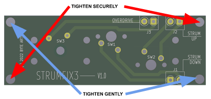
In this example, the RED arrows point to the screws that would be tightened firmly, while the BLUE arrows point to screws that should be gently tightened. The screws pointed to in BLUE just need to be tight enough to keep the circuit board from “rocking”.
If there is a lot of play and the circuit board and it doesn’t want to sit flat on the mounting posts, double-check that the strummer area is well-supported and is flat, then try again. You can also leave out one of the screws – three screws is enough to hold the strummer in place securely while reducing the chance of the board getting warped.
